Project Background
Once New-Line Equipment Arrived, the Existing Load List No Longer Explained Restart Risk
The original backup system covered control panels, lighting and a few critical machines, with stable monthly test records. A second line added compressors, cold-room equipment, conveyors, packaging machines, main motors and PLC panels. The first approach was simply to add nameplate ratings and increase generation by the resulting total.
During commissioning planning, the equipment engineer reframed the issue around restart order: energize controls first, restore utilities second, then start main motors and packaging. Compressor loading, refrigeration recovery, motor starting, PLC power-up and control-network reconnection create different transients. Without sufficient response and stable output, the new line would remain trapped in resets, alarms and recommissioning.
The core of a plant-expansion project is validating the generator with the restart sequence, not merely adding kW figures.
Challenges and Requirements
Starting Transients, Stable Output, Fuel Cost and Line Recovery All Converged on the Generator
Motor and compressor starting was the most underestimated added load. Nameplates describe steady operation; starting places much greater pressure on engine governing, alternator regulation, breakers, cables and switchboards. If refrigeration, compressors, pumps, fans and main motors recover without a defined order, voltage dips can repeatedly reset PLCs and control networks.
The plant also had to manage operating cost and maintenance pressure. Standby sets run many tests but few real loaded hours; low-load operation, weak cooling, fuel management and battery condition all affect future reliability. The expansion therefore required stable starting, load response, serviceable construction and expansion margin, with test records shared by maintenance and production.
Fast start response, stable voltage and frequency, staged-load capability, adequate cooling and a clearly defined fuel system.
Restore PLCs, compressors, refrigeration, pumps, main motors and packaging to the production restart rhythm.
Keep controller logs, running hours, alarms, batteries, fuel level, coolant and spare-parts lists continuously reviewable.
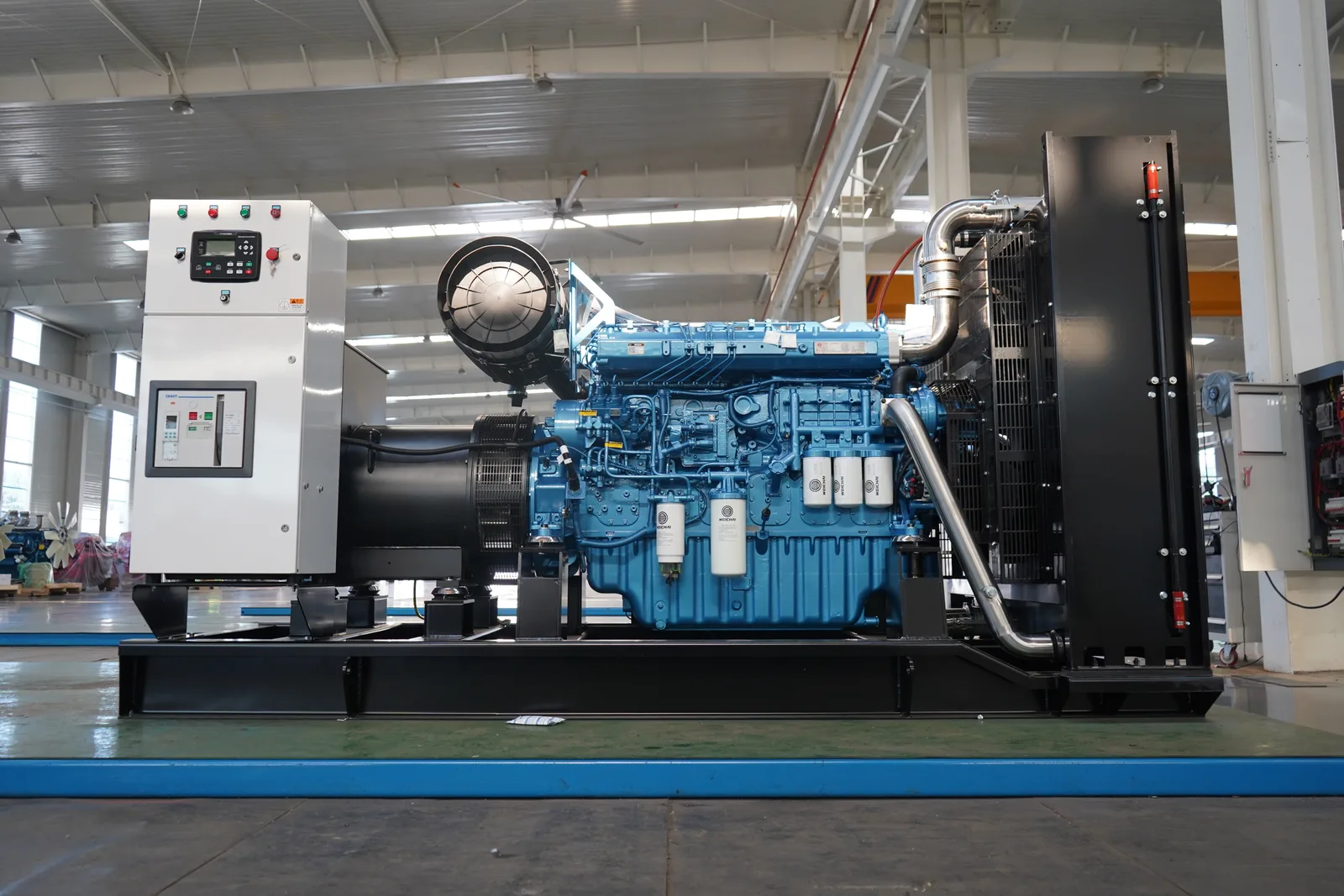
Generator-Set Solution
Select the Generator for Starting Transients, Stable Output, Fuel Efficiency and Serviceability
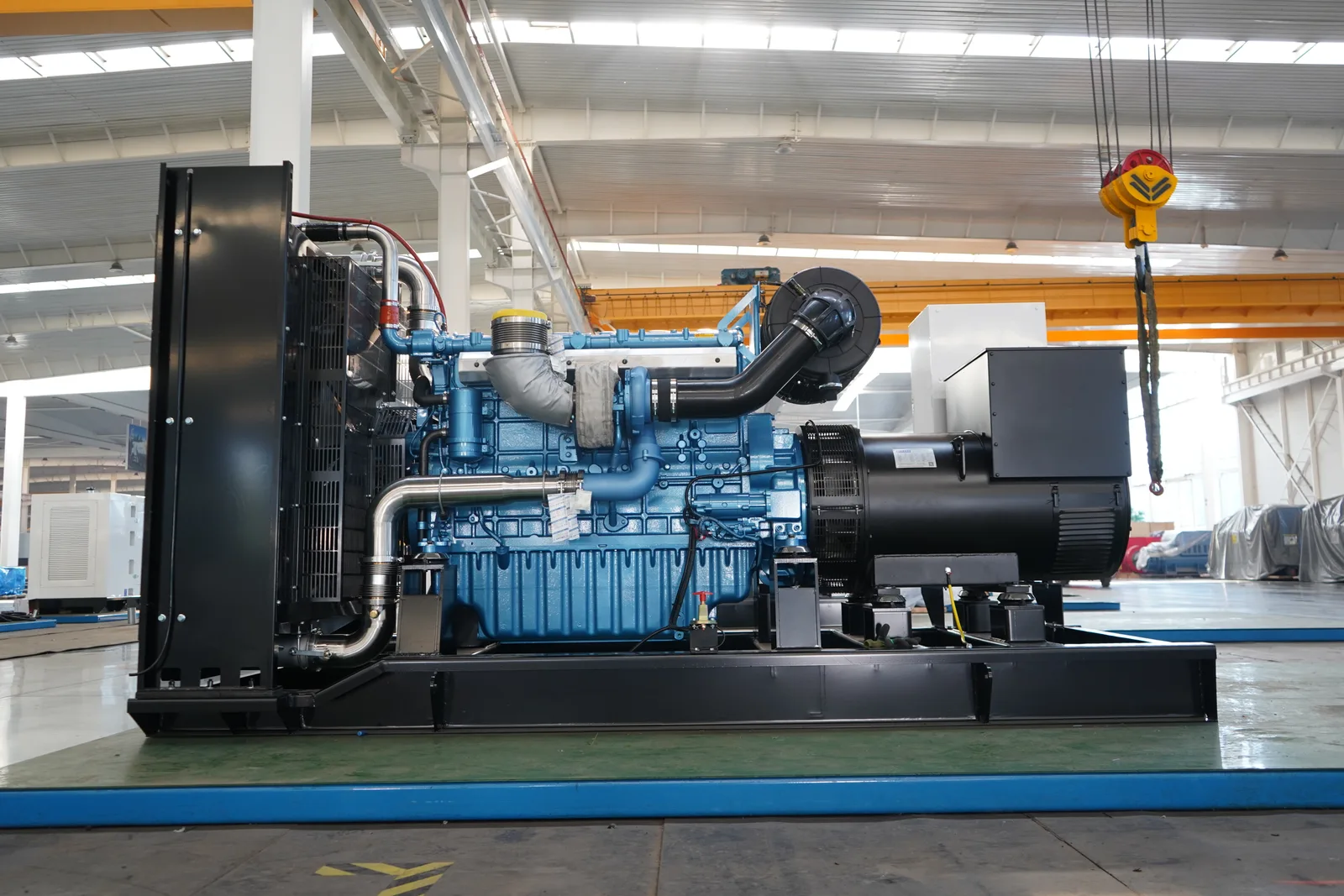
The diesel generator is the core of expansion backup. The engine must start reliably and maintain speed response as compressors, refrigeration and main motors connect in stages. The alternator and AVR must limit voltage and frequency variation to prevent resets in PLCs, drives, sensors and control power. The controller must retain start, load, alarm and shutdown data for maintenance troubleshooting.
Fuel use was assessed against testing and restart duty. Factory standby sets often operate in periodic tests, low-load maintenance and short loaded runs; oversizing increases fuel, service and carbon-deposit pressure. Start order, staged loading, shifts, future expansion and service windows were used to balance capacity with operating cost.
Complete-set quality also covers cooling, fuel, wiring, base frame, controls and service clearance. Open or enclosed construction depends on ventilation, exhaust, noise limits, forklift routes and service location. A generator is not a power figure; it is the combined behavior of engine, alternator, controls, cooling, fuel and installation conditions supporting production recovery.
- 01Assess start response across engine, alternator, AVR, controller and breaker as one transient chain.
- 02Assess fuel use across testing, low load, staged loading, shifts and future expansion.
- 03Assess long-term reliability through radiator, fuel lines, wiring, base, control panel and consumable access.
Power-System Solution
ATS, Low-Voltage Zones and Staged Loading Followed the Restart Sequence
After selecting the generator, engineers split loads into three tiers. PLCs, control power, industrial networks, sensors, safety and essential lighting stabilize first. Compressors, pumps, refrigeration, cooling and process water recover next. Main motors, conveyors, packaging and deferrable auxiliaries connect in stages.
ATS scope, switchboard feeders, breakers, cables and grounding were aligned to that order. Continuous and cold-chain processes also required review of temperature risk, downtime loss, storage buffering, fuel runtime and expansion interfaces. Load-test records covered generator start, ATS transfer, PLC power-up, compressor loading, refrigeration recovery, staged motor starts and voltage-frequency behavior.
PLCs, control power, industrial networks, sensors, safety systems and essential lighting.
Compressors, pumps, refrigeration, cooling, process water and critical utilities.
Main motors, conveyors, packaging, noncritical lines and deferrable auxiliaries.
Professional Engineering Services
From the Added-Equipment List to Loaded Start-Up, Engineering Validated Generator and Line Together
Pre-start inputs included the added-equipment list, starting methods, existing generator data, switchboard photographs, ATS scope, breakers, cables, PLC panels, compressed air, refrigeration duty, shifts and outage losses. Outputs defined generator configuration, staged-load order, parallel-system provisions, storage coordination, low-voltage feeders and fuel runtime.
After equipment arrival, service shifted to installation and commissioning: vibration isolation, airflow, exhaust, fuel, grounding, controls, low-voltage interfaces and access were checked item by item. Start-up testing recorded no-load start, staged loading, start intervals, voltage and frequency, oil pressure, coolant temperature, protections, abnormal resets and corrective actions so maintenance and production shared the same recovery evidence.
- 01Before arrival, confirm dimensions, lifting route, foundation, exhaust, cooling and service space.
- 02During installation, confirm fuel lines, cables, grounding, controls, ATS interfaces, switchboards and circuit labels.
- 03At handover, confirm starting, loading, PLC power-up, compressor loading, refrigeration recovery and operator handoff.
After-Sales and Operations Support
After Start-Up, Continue Tracking Hours, Alarms, Fuel Use and Load Records
After handover, maintenance rhythm determines whether the set can keep supporting line changes. Hours, starts, load factor, fuel use and level, battery voltage, coolant, controller alarms, ATS state, room ventilation and switchboard photographs belong in a fixed inspection record.
Spares were planned by generator model: filters, belts, starting batteries, sensors, chargers, controller parts, common electrical items and consumables. When lines, shifts or refrigeration capacity change, engineers can update staged loading from the original test evidence rather than leave backup power frozen at one-time handover conditions.
Results and Feedback
The Plant Gained a Generator That Handles Transients and Evidence for Line Recovery
After the adjustment, backup power changed from an equipment addition into a pre-start recovery plan. Maintenance could explain how the generator handles transients, why loads connect in that order, how fuel and testing are managed, how circuits are labeled and who owns future records.
The result was visible in practical terms: generator starting and stable output had evidence, PLC and utility recovery order was clear, refrigeration and compressed air connected more reliably, tests were traceable, and maintenance could evolve with line changes. That came closer to the real recovery objective than simply adding equipment.
Good factory backup construction places the generator, low-voltage distribution, restart order and operating records on one evidence chain.