Total capacity is high and one large generator would become a single dependency
Several sets share the load, leaving partial or full critical-load capability when one unit is maintained or unavailable.
Power-System Component / Capacity and Redundancy Management
When one generator should not carry the entire capacity, or the project needs N+1 redundancy, phased expansion and automatic start/stop by load, a paralleling system coordinates multiple sets, breakers, controllers and a common busbar as one power source.
Why Choose a Paralleling System
The customer value is not simply added capacity. It is an executable strategy balancing capacity, availability, operating efficiency and maintenance windows.
Several sets share the load, leaving partial or full critical-load capability when one unit is maintained or unavailable.
Run only the sets needed by current demand and reserve controller, busbar and switchboard capacity for future units.
Sets with different voltage, frequency, phase sequence, governing or excitation characteristics cannot be combined by adding a paralleling panel alone.
Utility-parallel operation involves reverse power, protection, metering and local interconnection rules and must be distinguished from islanded paralleling.
Complete Sequence from Start to Exit
Starting several generators is only the beginning. The system must decide how many sets are needed, connect each under acceptable conditions, share power stably and remove units according to the operating strategy.
The controller uses source status, bus load and operating strategy to determine how many sets should run.
Check start status, batteries, oil pressure, cooling and alarms so an unavailable set does not enter the synchronization sequence.
Speed and excitation are adjusted automatically; the breaker can close only when synchronization conditions are met.
The breaker makes the electrical connection while the controller confirms position and bus status and manages abnormal closing.
Sets carry the load together while balancing loading and running hours and avoiding prolonged light-load or overload operation.
As demand falls, a set unloads and opens in sequence, then cools down and stops while events and run records remain available.
System and Operating Configurations
Projects do not share one fixed paralleling-panel design. Capacity, redundancy level, operating mode and expansion plan should be defined before set quantity, switchboard lineup and control boundaries.
Several sets share total load where one unit is not large enough or loads should be brought online in stages.
One reserve unit is added beyond the N generators needed for the target load, preserving margin for a fault or maintenance.
The first phase serves current demand while reserving generator, busbar, breaker, communications and panel space for future units.
Islanded systems supply loads independently. Utility paralleling requires separate protection, metering, reverse-power and approval review.
N+1 is not simply an extra generator. Target load, largest-set capacity, maintenance scenarios and single-failure boundaries belong in the calculation; otherwise the reserve unit may not cover the actual system gap.
Capacity and Critical Parameters
There is no universal power table for a paralleling system. Each set's ratings, control characteristics and breaker conditions must be reviewed against the complete system.
Switchboard Design and Customer Value
Customers do not need to learn the control program, but they should understand how sources are measured, sets close, power is shared and faults are isolated and recorded.
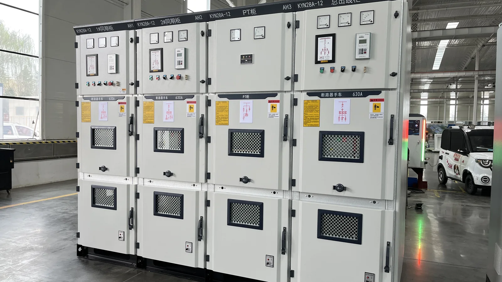
Executes starting, synchronization, closing, load sharing, unloading and stopping sequences.
Compares the incoming generator with the bus to prevent damaging out-of-sync closing.
Connect and isolate each generator circuit while coordinating protection, interlocking and position feedback.
Busbar section, support, clearances and connection torque influence temperature rise and short-circuit withstand.
Coordinates governing and excitation so sets share kW and kvar without one unit taking disproportionate load.
Responds to overcurrent, reverse power, abnormal voltage/frequency and breaker-closing failure.
Terminal identification, wire numbers, circuit separation and power redundancy affect commissioning and maintenance efficiency.
Provides status, load, alarm and event data to remote monitoring for traceability and run-hour balancing.
Six Project Inputs
Provide critical load, maximum demand, normal variation, starting steps and loads that can be delayed.
Provide engine, alternator, controller, rating, voltage, frequency, governing and excitation information.
Define current and future capacity, target redundancy level and the date each phase must enter service.
Review existing switchgear, breakers, fault level, selective protection, cable entry and service space.
Define islanded or utility-parallel mode, auto/manual control, thresholds, rotation, unloading and remote-control boundaries.
Define test methods and record ownership for synchronization, load sharing, one-set failure, N+1, unloading and recovery.
Typical System Tasks
Data centers, hospitals and large commercial facilities include target critical load, largest-unit loss and fault isolation in the design.
Factories, campuses and mixed-use developments add sets as demand grows, avoiding excessive first-phase capacity and later switchboard replacement.
Where demand varies through the day or production cycle, automatic start/stop, load sharing and run-hour balancing improve utilization.
Share existing and new generator data, critical loads, current and future capacity, redundancy level, single-line diagram, operating mode and commissioning window. HOHANK engineers will define set quantity, control boundaries, switchboard lineup and test scope.