A critical facility must run for several hours or longer
Hospitals, data centers, factories and commercial facilities need a direct relationship among target runtime, critical load and fuel reserve.
Power-System Component / Extended Runtime
A generator that starts has solved only the first minutes of an outage. A dependable fuel system combines consumption, usable tank capacity, supply and return lines, automatic transfer, level alarms and delivery access so standby power can continue safely.
Why Add a Fuel-Autonomy System
The customer value is not simply a larger tank. Fuel volume must be calculable, flow must remain continuous, refueling must be practical, abnormalities must raise alarms, and fire, environmental and inspection boundaries must be clear.
Hospitals, data centers, factories and commercial facilities need a direct relationship among target runtime, critical load and fuel reserve.
Day-tank capacity, bulk storage and replenishment intervals reduce the risk of a second shutdown while a delivery is delayed.
Actual load factor, unusable volume, return flow, minimum level, fuel temperature and contingency reserve change real runtime.
Tank location, pumps, valves, vents, overflow, spill containment, fire separation and tanker access must be reviewed together.
Complete Path from Storage to Engine
Failure at any interface can stop a project that still has fuel in storage. Every stage should match the engine's supply-and-return limits, the control sequence and the site's safety conditions.
Use the engine's consumption curve, load profile, starting and no-load time while reserving unusable volume and operating margin.
The near-engine tank stabilizes supply while external storage provides longer autonomy under the site's space, code and maintenance limits.
Supply and return lines must meet the engine's flow, lift, restriction and cleanliness requirements.
Low level starts transfer and high level stops it, while pump failure, overfill, valve position and interlocks generate alarms.
Storage areas, wall penetrations, grounding, static control, bunding and fire separation follow the site rules.
Define the fill point, vehicle position, operator steps, reorder level, supplier response and severe-weather contingency.
Product and System Configurations
Do not begin with one fixed tank capacity. First define consumption, operating time, available space and expected delivery frequency, then select the tank hierarchy and control method.
For short standby periods, compact spaces and easy delivery access. External piping is reduced, but usable volume and service access still need verification.
Provides stable supply near the generator and can combine with bulk storage, transfer pumps and level controls for easier daily inspection.
Provides the main reserve for prolonged outages and is located around safety distances, foundations, corrosion protection, bunding, venting and tanker access.
Duty/standby pumps, filters, valves, level control and alarms feed one or several generators for extended operation and centralized supervision.
Every capacity should be reviewed against engine-manufacturer consumption data, project load factor and local fire and environmental rules. This page does not promise a fixed consumption rate or fixed runtime.
Fuel Economy and Runtime Matching
Fuel economy cannot be judged from one catalog number. Engine platform, generator sizing, actual load factor, idle time, maintenance condition and fuel quality together determine the cost of delivered electricity.
Tank, Piping and Control Details
Customers do not need to design a fuel system, but they should be able to verify tank material, interfaces, level devices, pumps, filtration, spill controls and test records so stored fuel can actually reach the generator.
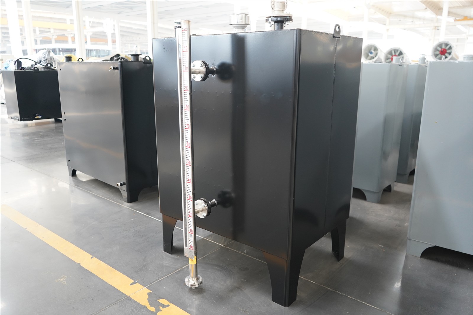
Material thickness, internal cleanliness, corrosion protection, welds and supports affect long-term storage and handling safety.
A local gauge supports quick checks while electronic sensors provide low, high and overfill alarms.
Connections should prevent pressure problems, water entry and spills during refueling.
Port sizes, location and piping restriction must match the engine and preserve water and sediment removal.
Flow, head, duty/standby changeover and filtration cover normal transfer and pump-failure conditions.
Isolation, non-return protection and a manual bypass simplify service and prevent siphoning, backflow and operating errors.
Spill containment, alarms, grounding, static control and fire separation follow the site's rules.
Level, pump state, alarms, transferred volume and run hours support inspection and fault tracing.
Six Project Inputs
Provide generator rating, engine model, expected load factor and fuel-use data at relevant load points.
Define minimum guaranteed hours, load priorities, sheddable equipment and the outage-duration assumption.
Share plant-room and outdoor storage locations, foundations, piping distance, level difference, access and environment.
Confirm vehicle size, parking position, fill connection, arrival time, delivery cadence and operator responsibility.
Define storage limits, separation, bunding, venting, grounding, drainage and local approval boundaries.
Define pump logic, alarm outputs, manual bypass, remote notifications and recording requirements.
Typical Runtime Tasks
Set minimum inventory from critical demand, UPS ride-through, cooling needs and tanker response, then verify it against level and run records.
Hotels, malls and schools balance runtime with noise, odor, fire safety, occupied areas and restrictions on refueling during operation.
Factories and remote sites plan around process loads, generator rotation, stored-fuel quality, standby pumps and supplier intervals.
Share generator rating and engine model, load factor, required hours, tank space, delivery route, fire and environmental requirements and monitoring needs. HOHANK engineers will define the tank hierarchy, pumps, valves, piping, alarms and test scope.