Critical and general loads are not yet separated
Life safety, fire protection, security, pumps, cold chain, controls, UPS loads and comfort loads need clear priorities and separate feeder boundaries.
Power-System Component / Protected Load Connection
Starting the generator is only the first step. The distribution system receives power from the generator, ATS or paralleling bus, then protects, meters and directs it to prioritized load circuits so critical equipment returns in the right order.
Why Distribution Design Matters
A generator rating does not reveal which circuits start together, which loads must recover first or how a downstream fault should be isolated. Those decisions belong in the distribution design.
Life safety, fire protection, security, pumps, cold chain, controls, UPS loads and comfort loads need clear priorities and separate feeder boundaries.
The project needs defined incomers, bus relationships, outgoing feeders, cable routes, protection coordination and service space.
Total kW does not show simultaneity, motor starting or restoration sequence and can lead to nuisance trips or generator overload.
Fault current, breaking capacity, selective protection, busbar withstand and grounding must also match the project and local acceptance requirements.
Complete Route from Source to Load
Every stage should correspond to the single-line diagram, control sequence and installed equipment. Otherwise adequate generator capacity can still be defeated by unclear interfaces, protection trips or simultaneous load restoration.
Confirm voltage, frequency, phases, available capacity, grounding method and fault conditions.
The main breaker isolates and protects the board while reporting status to upstream and downstream controls.
Segment the bus around capacity, operating modes and fault boundaries so one fault does not remove every critical load.
Each breaker is selected around equipment current, cable capacity, starting method and protection requirements.
Restore life-safety and control loads first, then add pumps, lifts, chillers and other large loads without creating a second overload.
Voltage, current, breaker status, alarms and events support routine inspection and fault analysis.
Switchboard and System Configurations
Do not start from one standard cabinet. First define the relationship among the generator, ATS, paralleling bus, existing low-voltage system and critical loads.
Connect one generator to a defined set of critical circuits with a main breaker, busbar, metering and feeder protection.
After the ATS selects utility or generator power, distribute standby supply to fire, security, pumps, UPS loads and essential equipment by priority.
Manage total capacity, fault isolation and area loads through a common bus, bus couplers and outgoing switchboards.
Combine incomers, control, distribution, cable interfaces and service space for new electrical rooms, outdoor packages and retrofit projects.
High-voltage output requires a separate review of voltage level, transformers, vacuum circuit breakers, relay protection, grounding and local acceptance rules. A low-voltage switchboard design should not be reused as a high-voltage solution.
Load Priorities and Critical Parameters
Low-voltage distribution is not a simple conversion from generator kW to one main-breaker current. Circuit simultaneity, starting demand, fault conditions, cable length and selective protection must be assessed together.
Inside the Switchboard
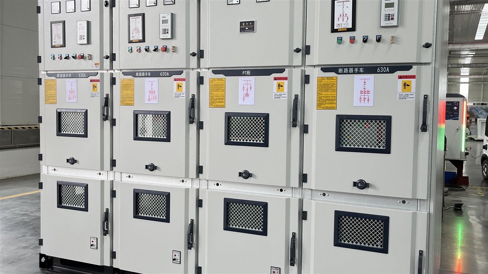
Customers do not need to design the switchboard, but they should be able to verify the main components, circuit labels, service clearances and test records before accepting the system.
Connects and isolates the source; rating and breaking capacity must match the system.
Organize sources and load zones while material, section, support and joints determine temperature rise and fault withstand.
Protect each feeder according to circuit current, cable capacity and equipment characteristics.
Show voltage, frequency, phase currents, power and breaker positions for operating decisions.
Responds to overcurrent, earth faults and abnormal voltage and coordinates with ATS and paralleling controls.
Clear terminal blocks, circuit identification and functional separation reduce commissioning and maintenance errors.
Strength, ventilation, protection, access and cable-bending space affect long-term maintainability.
Single-line diagrams, settings, insulation, function and loaded-test results create a traceable handover.
Six Project Inputs
Provide capacity, voltage, frequency, phases, operating mode, grounding and connection location.
List operating current, starting method, simultaneity and required restoration order for each load.
Share existing drawings, panel photos, breaker models and settings, and available cable information.
Confirm delivery access, installation dimensions, service clearances, cable trenches, entry direction and environment.
Define planned loads, spare ways, busbar margin, terminals and phased-implementation boundaries.
Define insulation, phase sequence, interlocks, protection, circuit verification and load-restoration test methods.
Typical Distribution Tasks
Separate no-break loads, UPS-backed loads and staged-restoration equipment while keeping faults locally isolatable.
Restore fire protection, security, emergency lighting, essential lifts and pumps first, then add other circuits within generator capacity.
Organize controls, cooling, drainage, compressed air and production loads in the process sequence to reduce voltage dips and trips.
Share source capacity, circuit loads and priorities, existing drawings, breaker and cable data, room dimensions, cable-entry direction and expansion plans. HOHANK engineers will define the switchboard lineup, protection, busbars, cabling and test scope.