For large capacity arriving quickly and taking over several critical feeders
Supports large factories, regional public facilities, major events and disaster repair with multi-feeder outputs, paralleling provisions, monitoring and extended runtime.
Typical Project Configuration · Customizable Range · 800kW
A high-capacity emergency power truck for major infrastructure, manufacturing and critical response. Multi-axle chassis, generation, cooling, exhaust, fuel, distribution, cables and vehicle compliance must be designed as one system.
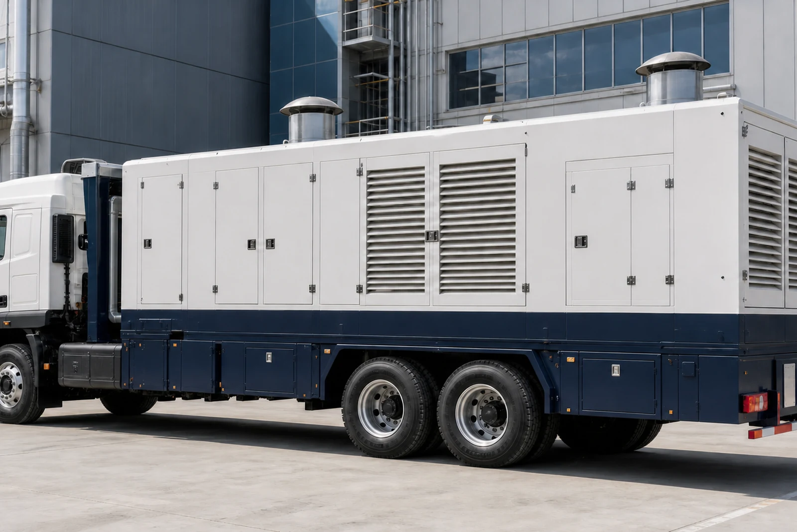
Product photos · Typical configuration
Typical 800 kW vehicle-mounted emergency station for infrastructure, factories and major response, covering multi-axle chassis, thermal management, distribution and site connection.
This page presents one typical project configuration to explain output, brand combination, package format and system interfaces. The same range covers additional outputs and options; the final engine model, rating, voltage, controller, tank, dimensions and supply scope are defined for the project.
Applications
Supports large factories, regional public facilities, major events and disaster repair with multi-feeder outputs, paralleling provisions, monitoring and extended runtime.
Gross vehicle weight, axle loads, route, turning and parking, ground capacity, hot-air discharge, exhaust clearance, high-current cables and protection coordination must be checked.
Core configuration
Engine, alternator, airflow and exhaust are engineered within the enclosed body for output, ambient temperature, transport restraint and safe hot-air discharge.
Chassis, gross weight, axle loads, center of gravity, brakes, tires, body dimensions and service space determine vehicle safety and compliance; output alone cannot select the truck.
LV distribution, breakers, terminals or sockets, quick connectors, cable reels, grounding and selective protection turn generating capacity into safely connectable feeders.
Controller, monitoring, fuel, refueling, task lighting, records and operating zones are organized around the response mission to reduce setup time.
Key parameters
These are the parameters that shape selection and interfaces. Fuel consumption, noise and dimensions are supplied after the engine model, load factor and site environment are defined.
| Reference output | 800 kW / 1000 kVA @ PF 0.8 |
|---|---|
| Rating basis | Prime/standby rating confirmed against the final engine model, ISO 8528 conditions and mission duration |
| Engine / alternator | Project-selected engine / Project-selected alternator |
| Vehicle platform | Multi-axle high-capacity truck |
| Vehicle compliance | Gross vehicle weight, axle loads, dimensions, turning radius, vehicle rules and registration boundary confirmed by project |
| Distribution / output | LV distribution, terminals or sockets, quick connectors, cable reels and multi-feeder protection configured for the task |
| Fuel autonomy | Vehicle tank or dedicated fuel system sized for runtime, refueling route and fire requirements |
| System interfaces | ATS, paralleling, remote monitoring, task lighting, grounding and operating records available |
Quality and delivery
Engine, alternator, controller and breaker brands, models and serial information are listed in the technical and delivery documents.
Base steel, welds, fasteners, mounts and coating are included in manufacturing inspection; container packages also cover doors, hinges, locks, seals and lifting points.
Radiator, airflow, wiring terminations, grounding, protection and safety separation support loaded stability and long-term serviceability.
Factory records can cover starting, no-load and staged-load operation, voltage, frequency, alarms and protection, with witnessed FAT available by project.
Project configuration
Provide the country and city, load list, frequency, voltage, duty, installation environment and required delivery. A HOHANK engineer will verify output, component selection, interfaces and the supply boundary.