Critical demand exceeds the economic range of one conventional set
Large hospitals, data centers, factories, commercial complexes and campuses usually need multiple feeders, load zones and complete auxiliary systems.
Large-Power Systems / Above 1MW
Above 1MW, the decision is no longer simply a larger engine. Load priorities, unit rating, paralleling, N+1 redundancy, voltage, distribution, fuel autonomy, cooling, exhaust, monitoring and maintenance windows must be confirmed as one system.
When Large-Power System Design Begins
One megawatt is a practical entry point, not a model boundary. Two smaller generators can form a system above 1MW, while one large set may still be unsuitable because of maintenance, starting demand or redundancy requirements.
Large hospitals, data centers, factories, commercial complexes and campuses usually need multiple feeders, load zones and complete auxiliary systems.
Multiple sets can enter by load and provide a practical path for N+1, maintenance windows and future capacity growth.
Starting demand, diversity, UPS and VFD behavior, power factor, environmental derating and future growth all change the requirement.
Paralleling switchgear, transformers, breakers, cables, tanks, refueling, ventilation, exhaust and testing often decide whether the system can be delivered.
Design Sequence from Load to System Capacity
A large-power system should not begin with a preset 1000kW model. Start from critical loads, required operating time, transfer window and failure consequences, then allocate capacity across generation, distribution, fuel and controls.
Record steady demand, starting current, harmonics, power factor and restoration order rather than connecting everything at once.
Total capacity may come from one large or several smaller sets; unit selection must also consider minimum stable load, efficiency and serviceability.
State which loads remain after any one set exits, how quickly reserve capacity enters and how a failed set is isolated.
Use capacity, distance, current, existing busbars and transformers to compare 400V, 6.3kV, 10.5kV or project-specific options.
Runtime, ambient temperature, altitude, space and local rules affect derating, enclosure and auxiliary-system requirements.
Acceptance covers starting, synchronization, sharing, load changes, set exit, transfer, protection, alarms and recovery.
Product and System Configurations
HOHANK can organize systems above 1MW around different engines, alternators, enclosures and controls. The page explains configuration logic rather than treating three fixed ratings as the entire range.
Fewer units and simpler controls, but single-point failure, maintenance outages, delivery, lifting, light-load operation and future expansion require review.
Synchronization, load sharing and automatic start/stop follow demand, improve part-load utilization and support maintenance and expansion.
For high-consequence facilities, reserve capacity, fault isolation, control redundancy and maintenance strategy must be proven together.
Where capacity is high, distance is long or the existing bus is medium voltage, evaluate 6.3kV or 10.5kV direct output or step-up connection.
Systems above 1MW may use 1–2MW-class single generators or parallel several medium and large sets for higher total capacity. Final rating, prime/standby definition, voltage and quantity follow the load study and project standard.
Ratings, Brands and Enclosures
Large projects can review Cummins, Weichai, Yuchai, Baudouin, Perkins, MTU and other engine platforms, paired with Stamford, Leroy-Somer, Marathon, Engga and other alternators. Coverage depends on rating, frequency, voltage, emissions and local service.
Eight Parts of a Large-Power System
Customers need not master every engineering detail, but they should be able to verify each module's responsibility, interfaces and test results so gaps do not appear between supply packages.
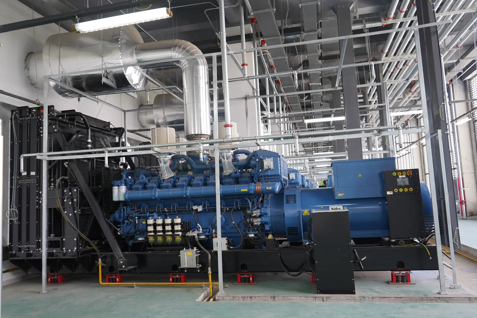
Verify prime/standby rating, frequency, derating, fuel use, emissions, service network and parts availability.
Confirm voltage, insulation, temperature rise, short-circuit capability, excitation, AVR and parallel operation.
Manages starting, protection, alarms, operating data and ATS or paralleling communications.
Executes synchronization, sharing, automatic dispatch, fault isolation, bus protection and priorities.
Routes capacity by load class and building zone with fault, selective and grounding protection.
Defines autonomy from required hours, day tanks, bulk storage, pumps, piping and local rules.
Verifies airflow, radiators, exhaust backpressure, noise, fire protection, service space and lifting.
Records operation, alarms, fuel, transfer and maintenance and completes load tests, training and spares handover.
Six Project Inputs
Provide load list, critical classes, starting methods, diversity, power factor, harmonics and planned expansion.
Describe utility conditions, annual hours, transfer window, critical interruption limits and restoration sequence.
Define capacity retained after one unit exits, expansion phases and the strategy during generator maintenance.
Confirm 50Hz or 60Hz, low or medium voltage, existing transformers, ATS/STS, breakers and cable routes.
Provide altitude, temperature, humidity, dust, noise, location, lifting route and emissions requirements.
Define autonomy, replenishment, remote monitoring, load-test conditions, site personnel, local response and spares.
Typical Large-Power Tasks
UPS, cooling, life safety, ATS/STS, fuel, monitoring, periodic tests and event records must prove capacity after one set exits.
Production lines, pumps, compressors, cold stores and utilities determine starting strategy; paralleling supports expansion and maintenance.
Multi-building feeder sequence, noise, fuel delivery, property operations and holiday testing belong in the system proposal.
Share country and city, critical loads, starting methods, expected capacity, 50Hz or 60Hz, voltage, redundancy, environment, fuel autonomy and expansion plan. HOHANK engineers will define unit rating, quantity, brands, enclosures, paralleling, distribution and auxiliary scope.